Do you have any questions? Need help?Call us +48 518 075 074


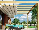
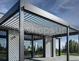
Installation of the Climatic lamella pergola
Before installation:
– Check compliance of the documentation with the condition of the elements
– Check the length of the profiles based on the documentation
– Compare the dimensions of the documentation with the existing installation site
– Prepare the installation site
Below is an example of the installation of Pergola Climatic

S=Total width of the pergola
W=Structure overhang1. Determine the total width of the structure and the projection on the ground.
2. Mark the attachment points for the ankles in the ground (tts.007.03 and tts.007.02).
3. Check the diagonals after marking the ankle attachment points in the ground.

4. Set the cubes tns.007.03 and tns.007.02.
5. Trace the anchor points in the ground.
6. Remove the cubes – drill holes.
7. Anchor the tns.007.03 and tns.007.02 cubes using a chemical anchor and m10x20 pins.

8. Anchor the tta.103 profiles with the tta101 profiles using two screws, from the inside of the structure, m6x40.

9. The resulting goal should be anchored on the ankles of the tta.007.03 and tta.007.02 legs, using Ampuł M6x10 screws.

10. Install the tta.101 guides to the tta.103 profiles and the tts.002 filling sheets.
Attention! In case of water drainage in the leg, before installing the tta.101 guides to the tta.103 profiles, install the tts.020.02 filling in the tta.103 profile

11. Anchor the gutter caps tta.003.04 using silicone to the tta.103 profile.
The gutter cap TTA.003.04 should be inserted from the inner side of the gutter into the TTA.104 profile, and then it should be pushed to the TTA.101 profile.
The connection point of the TTA.104 gutter with the TTA.103 support profile and the TTA.003.04 gutter cap should be siliconized.
Possible configurations:
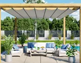
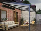
Climatic Wall Pergola
Includes:
Installation of the guide directly to the facade, using wall brackets.
Anchoring the leg profiles on standard leg ankles in the ground, using water spouts or direct water drainage into the ground.
Gutters draining water directly to the profiles of long leg profiles.

1. To mount tta.101 guides to the facade, use wall brackets
Tts.010 – (tts.010.01 and tts.010.02).
2. Install the remaining profiles in accordance with the rest of the instructions.
Possible configurations:
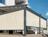
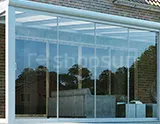
Climatic Modular Pergola
Includes:
Standard assembly of profiles.
Anchoring the leg profiles on standard leg ankles in the ground, using water spouts or direct water drainage into the ground.
Installation of guides to leg profiles using screws from the inside of the structure.
The central guide is surrounded by gutters on both sides.

1. Mount the middle guide to the middle leg using Ampul M6x40 screws.
2. To install the remaining profiles, proceed as follows
Instructions.

The gutter cap TTA.003.04 should be inserted from the inner side of the gutter into the TTA.104 profile, and then it should be pushed to the TTA.101 profile.
The connection point of the TTA.104 gutter with the TTA.103 support profile and the gutter cap TNA.003.04, respectively, should be siliconized
Possible configurations:
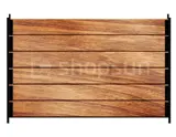
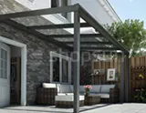
Pergola Climatic Wall-mounted Perpendicular slats
Includes:
Installation of one of the guides to the facade using special wall brackets.
Anchoring the leg profiles on standard leg ankles in the ground, using water spouts or direct water drainage into the ground.
Roof profiles arranged perpendicular to the façade.
Possibility of using an innovative profile connection using a short leg.
A gutter profile runs around the structure to drain water through longer leg profiles.

1. The gate created after assembling the TT.103 profiles should be anchored on the ankles of the TTS.007 legs.
Tta.101, using two M6x40 screws from the inside of the structure.
2. Use the tts.019 brackets to attach the tta.101 profile to the façade.
3. The tts.019 holder should be mounted using M12x2 threaded rods to the facade.


15. Install the tta.106 slats to the tta.101 guide onto the ttt.206 pin.
15.1. Rotate the slats for installation by an angle of less than 90° in relation to the full opening of the slats (Fig. 1).
15.2. The profile assembly should start from the opposite side, in order to place it in the TTA.101 guide hole, at an angle. After partially securing it in the appropriate hole, push the profile to lock it and turn the profile to the closed position (Fig. 2).
15.3. After mounting the profile in the opposite guide, repeat the installation of the profile in the motor guide (Fig. 3).
15.4. In the case of slats with LED points, connect the cable using a connector and then throw the whole thing into the guide profile (Fig. 2 – view 2).

16. Install the tta.107 slat fastening profile using slat pins.

17. Zamontować zaślepki nogi tta.102 i tta.001.02.
18. Zamontować zaślepkę tta.102 dla profilu tta.103.

Final assembly of the TTA.105 profile with TTA.104
19. Installation of additional options:
19.1 installation of the tta.105 LED profile on tta.104