Do you have any questions? Need help?Call us +48 518 075 074
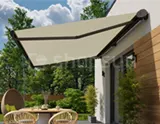


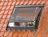


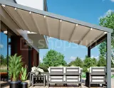


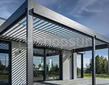
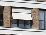
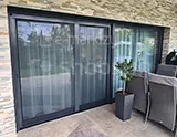
Installation of Square Wall Pergola
Pergola installation Square Wall (short version)


Installation of the Square Wall Pergola (full version) – Square pergola assembly instructions

1. The delivered pergola structure is custom-made in accordance with the order. The installation of the pergola on the facility must be carried out in accordance with the dimensions specified during measurements. A dimension card is provided with each product. The purpose of the penalty is to determine the location of structural profiles, the correct installation of which will ensure the correct angle of inclination of the pergola and, therefore, proper drainage of rainwater. The presented dimensions will make it easier to plan the location of holes drilled in the wall and in the ground. Characteristic dimensions of the pergola:
– projection: distance from the wall to the outer surface of the columns,
– width: distance between the outer surfaces of the pergola rails,
– front height: the amount of light between the ground and the bottom of the gutter,
– mounting height: the distance from the ground to the bottom of the wall bracket, measured at the wall.
Note: The pergola assembled by the manufacturer has no programmed motor end positions. Only after attaching the fabric and screwing the fixed beam, the installer can program the end positions according to the instructions of the selected drive.


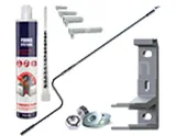
2. Installing a wall pergola requires preparing holes in the wall for the wall rail bracket and for the feet of the front columns. The dimensions of the bracket and foot are shown in the drawings.

3. First, attach the wall brackets to the wall through the oblong (bean) holes. When installing the bracket, make sure that the holes connecting the rail are located at the bottom of the bracket. The brackets should be mounted at a specific mounting height and spaced according to the distance resulting from the width of the pergola.


4. Pre-screw the column feet to the ground. At this stage, they should not be screwed completely – this will leave the possibility of adjusting the final dimension of the structure. During installation, place the poles in such a position that the connecting sheets with the gutter face inwards and the drainage channel faces from the front of the pergola. The nominal position of the poles depends on the reach and width of the pergola.

5. Place a gutter on the standing poles. The gutter will be connected using conical screws and M10 flat nuts. M10 flat nuts should be inserted into dedicated gutter channels (2 nuts per pole).


6. Before mounting the rail, verify whether the tensioning trolleys (i.e. trolleys permanently connected to the belt) are synchronized on all rails. The manufacturer delivers the rails synchronized with the tensioned belt. To check this condition, place the rails side by side and move the carriages to an identical position along the rail (dimension A=B), then it will be possible to simultaneously insert the square pin through the drive heads of both rails. When passing the square pin through the drive wheels in the head, make sure that the triangular marking on both wheels is in the same angular position. If the carts are not synchronized:
– leave the square pin inserted through both heads,
– remove the rail cap,
– loosen the toothed belt by unscrewing the belt adjustment screw in one of the rails,
– equalize the position of the tensioning trolleys,
– tighten the belt,
– check the mutual position of the tensioning carriages again.

7. Connect the rails with the wall brackets and the hinges mounted on the gutter. The system includes right, left and middle rails, which differ in the position of side seals. During installation, make sure that the seals face the inside of the pergola.


8. Insert collared sleeves into the drainage holes and seal them with silicone.

9. Screw the caps to the gutter. Seal the gutter-cap connection from the inside with silicone.
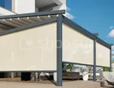
Note: In the case of a pergola with a ZIP roller shutter, the cap will only be installed under the gutter after the roller shutter has been installed.

10. Fasten the transverse poles: engine beam and roof support.


Fasten the cross posts at a specific position along the rail. The motor beam for each pergola has the same position: it is 41 mm measured from the front of the rail profile (measuring base A). However, the position of the canopy support will depend on the canopy projection. The standard roof in the pergola system has an overhang of 80 cm and for such an overhang the position of the canopy support beam will be 500 mm from the front of the rail profile (measurement base A).

11. The engine beam is delivered with a screwed engine box (i.e. a gearbox made of a tubular engine hidden in the cassette). It is possible to assemble the beam separately and then attach the engine box to it. The engine box is tightened to the rivet nuts connected to the beam.
To ensure proper operation of the drive system, the engine box must be properly positioned relative to the drive head:
– the arrow on the side of the box should point upwards,
– the engine box bracket should hang on the top screw core (on surface B) through the upper bean hole,
– the engine box should extend slightly (about 1 mm) beyond the engine beam (measuring base C).
12. After attaching the crossbeams, you can tighten the foot screws from point4of the instructions.

3. Depending on the production order, the drive for the delivered product is located on the right or left side of the pergola. The engine box is attached to the engine beam at a distance of 700 mm from the rail profile.
Steel winding tubes are used to transmit torque from the engine box.
Note: Before installing the pipes, make sure that the tensioning carriages are in the same position along each rail!


Insert the sliding pin into the drive wheels inside the head – the pin should go through the entire drive wheel. Position the pipes so that the pipe head is approximately 35 mm from the side of the engine box.
Note: When inserting the square pin into the drive wheels, limit the rotation of the pipe to
Determine the position of the drive tubes by tightening the pressure screws.

14. Insert the fabric bundle with beams into the pergola rails. The package is connected to the rail by inserting the trolleys into the service hole in the head. Fabric beams 1÷5 are introduced successively (their number depends on the pergola’s reach – in the example discussed there are 7 beams in total in the package) and finally the fixed beam 6. Tension beam 7 is the only one without a bolted trolley, as it is permanently connected with toothed belt inside the rail.

Once all the carriages have been inserted, connect the tension beam to the tension carriage. The connection is made by inserting the beam assembly axis through a hole in the fabric and beam profile. Then, put the pressure sleeve on the assembly axis through the hole in the bottom of the beam and screw the M6 flange nut onto the axis thread. After twisting the beam with the tensioning trolley to some extent, press the beam cap into the profile.

15. Lock the fixed beam at a distance of 150 mm from the face of the rail profile (measurement base A). The lock is achieved by twisting the pressure plates: external and internal.
Note: The pergola assembled by the manufacturer has no programmed motor end positions. Only after attaching the fabric and screwing the fixed beam, the installer can program the end positions according to the instructions of the selected drive.

16. Screw the covers to the rail heads.

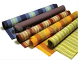
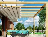
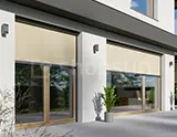
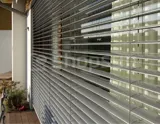
17. The drive system will be hidden by a fabric curtain. The curtain is attached to the wall (or ceiling) with a hanger. The number of hangers depends on the width of the pergola. Attach external hangers to the wall under the heads.

Then insert the curtain into the lower channel of the fixed beam and the channel in the wall profile. After inserting the fabric, close both profiles with appropriate caps. Hang the wall profile on hangers.
Canopy Installation – See Page
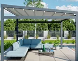
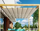
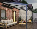
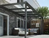
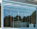
The page concerns a terrace pergola Square by Mol made to measure in accordance with the information provided during the order in the product configurator. More information can be found in the configurator or on other product subpages.
Installation of a square wall pergola - Installation of a square terrace pergola, pergola assembly instructions, how to install pergolas, Pergola square, installation of a protective canopy, pergola system canopy, installation instructions, pergola fabric cover installation, Terrace pergola square assembly instructions. installation of a terrace pergola, Pergola square pergola foot, technical data of the pergola, cross-section of the foot, Pergola square wall bracket for pergola rails, technical data of the pergola, cross-section of the bracket